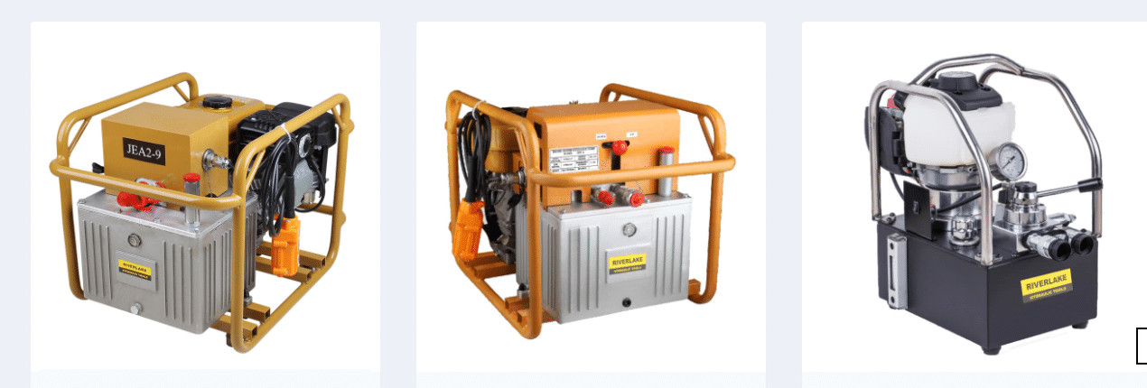
In hydraulic systems, pressure control is performed by metering the flow of a fluid into or out of a confined volume. Pressure controllers are not relief valves or pressure-reducing valves. They limit or lower pressure, but they don’t actually control it to the appropriate level. Only a specific ratio of pressure can be reduced via pressure-reducing valves. The input pressure determines the output pressure. Relief valves merely set a pressure limit. Another disadvantage of these devices is that they rely on springs and are only proportional control. They don’t have rate control or the capacity to switch between pressures on the fly.
Due to the Bernoulli effect, when oil flows at a high rate, the detected pressure will be low. The Bernoulli effect asserts that while the sum of kinetic energy, potential energy, and internal energy of a flowing fluid remains constant, the static pressure of the fluid falls. As a result, pressure sensors should be used in dynamic applications where fluid flow is not fast or turbulent. Pressure, force, and position can all be controlled by some gas-powered hydraulic power pack motion controllers. Diagnostics, control algorithms, and the capacity to coordinate several valves at once are all advantages of these controllers. This is required for applications such as hydroforming, in which oil pressure changes rapidly when compressed or decompressed even little. Rapid response and the capacity to metre oil in and out of a compressed volume of oil are required in these types of pressure-control applications.
When you add fluid to a specific volume, the pressure rises, but when you let it out, the pressure falls. There is a common misperception that the pressure gain curve of the valve controls the pressure. This is only true in a testing scenario, where pressure sensors are directly attached to the valve’s A and B ports. Under compression, there is no oil volume. Another common misunderstanding is that “pressure” means “barrier to flow.” It would be more accurate to say that a drop in pressure is caused by a resistance to flow. Another issue is that pressure is proportional to the fluid’s internal energy. A flow resistance does not add energy to the system, but it does dissipate energy in the form of heat. Another common misperception is that pumps create flow rather than pressure.
Control of electro-hydraulic proportional or servo valves is normally accomplished with the help of a power unit that keeps the control valve’s inlet pressure constant. A design strategy like this has a lot of benefits, but it also has a lot of drawbacks:
When a signal to open the valve is delivered, hydraulic power is immediately accessible with a high-pressure source. That is, there is no need to wait for the pump to reach full pressure before the load moves.
Because nearly all servo and proportional valves have a closed-center center-spool position, they can be employed.
A pressure-regulating supply is required since the valves are closed in the middle. When it comes to regulating pressure, pressure-compensated pumps are a popular choice. Regulating the valve supply pressure to the smallest practical tolerance achieves the highest precision. That is, regardless of the load’s variation in flow demand, supply pressure is maintained constant.
In the face of flow demand fluctuations that can rapidly increase from zero to maximum, a pressure-compensated pump may be able to produce hydraulic power at a reasonably constant pressure. However, it’s possible that it won’t. An accumulator may be used to supplement pump flow during brief periods of peak flow needs, depending on the circumstances. However, in many cases, the pressure-compensated pump will be sufficient.
The pump utilized in the testing is marketed as having a response time of roughly 145 milliseconds. To put it another way, it can go from zero to full stroke in that time. As a result, a simple rule of thumb is required to assist designers in determining when an accumulator is absolutely necessary and when it is not. Only the time required to modify the flow in the application must be compared to the published pump reaction time. In one of the tests, it took 0.6 seconds to get from zero to maximum demand flow. The response time of the pump is four times longer. The increased cycle-rate profile, on the other hand, lowered the flow rise time to only 150 msec, resulting in an evident performance failure.
To determine if you can get by without using an augmenting accumulator in conjunction with a pressure-compensated pump, follow this rule of thumb: If the flow change time from zero to maximum flow, or from maximum to zero flow, is three times or more than the pump’s whole stroke reaction time, no accumulator is required. With its reduced cycle time, this application could benefit from an accumulator. The opening of the valve at the flow-increase time would use the flow from the accumulator to meet the unexpected flow demand if an accumulator was fitted. This is true not just for discharging but also for refilling the accumulator. The accumulator reacts to quick variations in demand while the pump changes displacement slowly to meet typical flow demands.


